

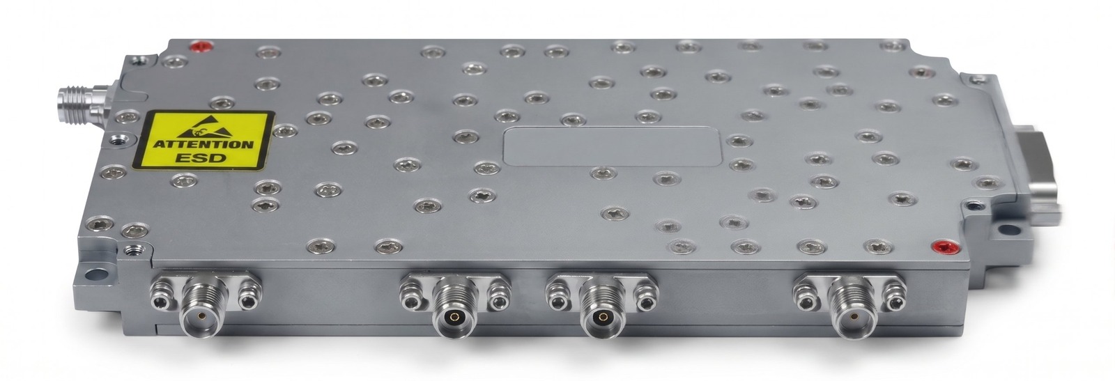
Dual-band up/down converter covering 18–40 GHz RF with 2–16.5 GHz IF, 14 GHz LO input, and fast band switching.
| General | |
|---|---|
| RF frequency | Band 1: 18 – 26 GHz; Band 2: 25.5 – 40 GHz |
| IF frequency | Band 1: 2 – 10 GHz; Band 2: 2 – 16.5 GHz |
| LO input | 14 GHz, +3 to +7 dBm |
| Operating temperature | -20°C to +70°C |
| Down Converter | |
| Gain | Band 1: 23 dB ±3 dB @ 2.4–9.6 GHz; ≥ 17.5 dB @ 2–2.4 and 9.6–10 GHz Band 2: 21.5 dB ±3 dB @ 2–16.5 GHz; ≥ 17.5 dB @ 2–16.5 GHz |
| Gain over temperature (-20 to +70°C) | Band 1: 24 dB ±4 dB @ 2.4–9.6 GHz; ≥ 17 dB @ 2–2.4 and 9.6–10 GHz Band 2: 22 dB ±5 dB @ 2–16.5 GHz; ≥ 17 dB @ 2–16.5 GHz |
| Input P-1dB | ≥ -6 dBm |
| Noise figure | ≤ 22 dB |
| Band rejection (RF to IF) | RF 18–26 GHz: ≥ 45 dBc @ 95% BW; ≥ 38 dBc @ RFin > 30 GHz; ≥ 35 dBc @ RFin < 16.5 GHz RF 25.5–40 GHz: ≥ 60 dBc @ RFin < 23.5 GHz; ≥ 55 dBc @ 95% BW; ≥ 50 dBc @ RFin > 44 GHz |
| IF harmonic (2nd, Pin = -35 dBm) | RF 18–26 GHz: ≥ 48 dBc; RF 25.5–40 GHz: ≥ 40 dBc |
| LO isolation at IF out | ≥ 50 dBc @ 95% BW; 46 dBc worst case |
| VSWR | Input 2.2:1 (2.2:1 @ 25.5–40 GHz over 95% BW, 2.4:1 max); output 2.2:1 @ 2–16.5 GHz |
| Image rejection | ≥ 50 dBc |
| Spurious | ≥ 50 dBc @ 95% BW; 47 dBc worst case, measured at IF output (Pin = -25 dBm) |
| Up Converter | |
| Gain | 30 dB ±3.5 dB @ 18–26 GHz; 30 dB ±3 dB @ 26.5–39 GHz 30 dB +3/-5 dB @ 25.5–26.5 GHz and 39–40 GHz |
| Gain window over temperature (-20 to +70°C) | 27.5 dB ±4 dB @ 18–26 GHz; 30 dB ±4 dB @ 26.5–39 GHz 30 dB ±5 dB @ 25.75–26.5 and 39–39.75 GHz; 30 dB ±6.5 dB @ 25.5–25.75 and 39.75–40 GHz |
| Input P-1dB | ≥ -9 dBm @ 18–26 GHz; ≥ -12 dBm @ 95% of 25.5–40 GHz; -13 dBm worst case |
| Noise figure | ≤ 20 dB |
| Band rejection (IF to RF) | IF 2–10 GHz: ≥ 35 dBc @ IFin > 12 GHz; ≥ 30 dBc @ IFin < 1 GHz IF 2–16.5 GHz: ≥ 35 dBc @ IFin > 18 GHz; ≥ 30 dBc @ IFin < 1 GHz |
| RF harmonic (2nd, Pin = -35 dBm) | ≥ 30 dBc |
| LO isolation at IF out | RF 18–26 GHz: ≥ 49 dBc @ 95% BW; 39 dBc worst case RF 25.5–40 GHz: ≥ 50 dBc @ 95% BW; 45 dBc worst case |
| VSWR | Input 2.2:1; output 2.2:1 @ 25.5–40 GHz (95% BW; 2.4:1 max) |
| Image rejection | ≥ 45 dBc |
| Spurious | ≥ 50 dBc @ 95% BW; 45 dBc worst case, measured at IF (Pin = -25 dBm) |
| Other Specifications | |
| Switching speed | ≤ 150 ns |
| Input power handling | +15 dBm CW |
| Internally generated spurious | ≤ -55 dBm (measured at input) |
| Isolation between sub-bands | ≥ 60 dB @ 90% BW; 55 dB worst case |
| Down-to-up converter isolation | ≥ 40 dB |
| Up-to-down converter isolation | ≥ 40 dB @ 90% BW; 34 dB worst case |
| Turn-on time | ≤ 500 ms |
| LO switching speed / isolation | ≤ 120 ns / ≥ 40 dB |
| LO input VSWR | 2:1 max |
| LO phase noise | typ. ≤ -76 dBc/Hz @ 1 kHz (worst case -82); ≤ -85 @ 10 kHz (worst case -91); ≤ -92 @ 100 kHz (worst case -97); ≤ -116 @ 1 MHz (worst case -122) |
| LO input switch | SPDT non-reflective switch required for the LO input |
| Power, Control & Interfaces | |
| Input voltage / current | 10 – 14 VDC / ≤ 1400 mA |
| Power consumption | 16.8 W @ +25°C; ≤ 19 W @ -20°C |
| TTL logic levels | “0” = 0 to 0.8 V; “1” = 2.4 to 5 V |
| No-damage conditions | Reverse polarity of supply voltage; any load VSWR (including short or open, any phase) at all ports |
| RF IN / RF OUT | 2.92 mm female (18 – 40 GHz) |
| IF IN / IF OUT | SMA female (2 – 16.5 GHz) |
| LO | SMA female (14 GHz) |
| Power & control connector | 50X-1013 circular connector (MIL-DTL-26482 square-flange receptacle) |
| Connector pinout | 1 SW DC in; 2 GND; 3 SW DC out; 4 GND; 5 SW UP in; 6 GND; 7 SW UP out; 8 GND; 9 SWLO; 10 +12 VDC; 11 GND; 12 NA; 13 GND |
Request a Quote or Datasheet
Tell us what you need and we will reply by email. You can also call +972-3-9067155 or write to sales@rmsl-tech.com.